


VFD Load Filters
VFD load filters or VFD load reactors?
In an earlier post we provided guidelines for selecting a general purpose line reactor. But what about load side VFD problems? When is it appropriate to add a load reactor? What is a VFD load filter? These questions are a little more difficult to address, but here goes.
At one time reactors were used to add load impedance in cases where the motor had a “low leakage inductance”. Over time, the higher carrier frequencies of IGBT drives all but eliminated the need to add inductance to the load. So when does it make sense to add a load reactor? Based on some of the potential issues, it may not make any sense at all.
Side effects of VFD load reactors
The reflected wave (or standing wave) problem associated with fast switching IGBT drives is often cited as the reason to apply a load reactor. Standing waves can create voltage spikes in excess of 1600 volts (480 circuit) at the motor terminals. This is particularly true when long motor lengths are involved (at as little as 200’).
Once the reactor is installed it will slow the rise time (change in voltage) of the spike, extending it over time (change in time). As a side note – a term often used to describe change in voltage over time is dv-dt. Getting back to the reactors, they cannot actively limit the voltage spike to a safe threshold (1000 volts). In cases of very long leads load reactors may have little to no impact. Load reactors can actually create problems, such as resonance from the inductive reactor and the capacitive cable.
VFD load filters
As stated before, the reactor can decrease the rise time of spikes, but cannot adequately limit the amplitude of spikes. Filters, on the other hand, add additional components (resistors and capacitors) that act to limit the actual amplitude, and therefore can have a much greater impact on motor health.
Dv/dt filters versus “sine wave” filters
VFD output filters begin with a reactor and are built out with additional resistive and capacitive components, forming a low pass filter. They are designed to limit the peak voltage to 1,000 volts. These filters are typically applied to applications lead lengths are up to about 1,000 feet.
A “sine wave” output filter goes another step beyond the dv/dt filter. These filters are “tuned” to the characteristics of the typical VFD output modulation, and effectively eliminate or greatly reduce the carrier frequency effects of modulation. These filters have been successful at lead lengths of up to 15,000 feet.
Benefits of VFD load filters
- Slow down the pulse dv/dt.
- Reduce common mode noise and currents (by as much as 30%)
- Increase bearing life
- Lower motor temperature
TCI – a good recommendation
We have used TCI reactors and power products for years. They are a Rockwell Encompass Partner and proven in industry. TCI offers both dv/dt and sine wave type filters, each backed by a performance guarantee.
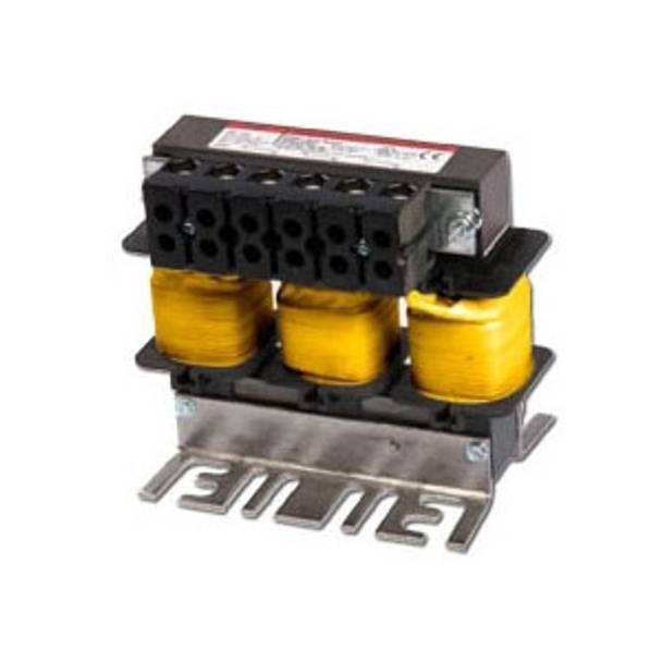
TCI® KDRD2P Ultra Low Optimized Drive Reactor, 480 VAC, 27 A, 20 hp, 5-3/4 in H x 7.2 in W TSKDRD2P
TCI® KDRD3P Ultra Low Optimized Drive Reactor, 480 VAC, 35 A, 25 hp, 5-3/4 in H x 7.2 in W TSKDRD3P
The TCI dv/dt filter
The KLC-Series V1k* filter was designed as an engineered solution for motor failures due to the reflected wave phenomenon. The V1K prevents voltage spikes from exceeding 1,000 V up to 2,000 feet and limits dv/dt to less than 1,000 V/ μs.
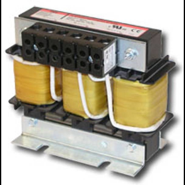
The V1k consists of two major components:
- The first part of the filter is a series line reactor which dampens the voltage distortion on the output of the VFD.
- The second component is a snubber circuit which effectively reduces the voltage distortion, dv/dt, to 1,000 volts per micro second on a typical 480 volt system.
This filter is very effective can protect standard and special service electric motors from the damaging effects of dv/dt. The V1k filter, however, does not return the drive output square wave to a sinusoidal waveform and thus is not referred to as a sine wave filter.
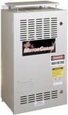
The TCI MotorGuard sine wave filter
The MotorGuard* greatly attenuates the carrier frequency voltage distortion and lowers the level of line distortion. These filters have been used on applications with lead lengths up to as much as 15,000 feet. Care should be taken when using the filter on vector drives, due to the feedback loop from the motor to the drive. The KMG requires the drive to have a carrier frequency of between 2 and 4 kHz.
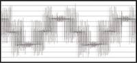
VFD output without filter
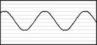
VFD output with sine wave filter
The MotorGuard consists of an R-L-C power filter circuit with:
- A TCI 3-phase reactor specifically designed for the MotorGuard Power resistors.
- High-endurance, harmonic-rated capacitors.
- Bleeder resistors to ensure safe capacitor discharge upon filter shutdown.
- Compression terminals for ease and integrity of all power wiring.
- Cooling fans to ensure adequate cooling and safe operating temperatures.
*information courtesy of TCI.