


Motor Repair Best Practices Part 2 – Insulation Resistance Test
Why is the Insulation Resistance Test Important?
Electrical testing of motors can be very complicated, yet its importance is often under-estimated. One of the most basic tests is the insulation resistance test, also referred to as the Megger test (due to the powerful Megger brand name). Though basic by nature Megger tests are very useful. However, if proper guidelines are not followed the results can be suspect. This post will explore insulation resistance testing and how you can get the most from it.
What is the Insulation Resistance test (IR)?
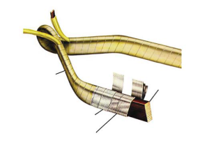
An insulation resistance test measures the integrity of the insulation system, sometimes referred to as the ground wall. A voltage is applied to a motor lead, with the frame of the motor serving as a ground reference. As the prescribed voltage is applied over a period of 60 seconds (which facilitates absorption) leakage current through the insulation to ground is measured by the meter. This leakage current is used to calculate the actual insulation resistance, usually measured in meg-ohms.
The IR test is part of standard proof testing and is also the first step in conducting a polarization index test, which requires a second reading to be captured at 10 minutes.
Applying the IR test
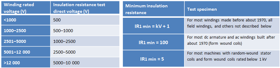
It is widely understood that if a motor tests as being “grounded” then there is definitely a problem. But what if readings have decreased, or are low? How low is too low? IEEE 43 provides the guidelines for applying the test, which varies depending on applied voltage rating. A 4160 volt motor would be tested at 1000 – 2500 volts. Per the standard, most form coil windings manufactured after 1970 should have a minimum of 100 meg-ohms for operation.
Precautions and considerations in applying the IR test
There are a number of precautions to consider when conducting an insulation resistance test, particularly personnel safety. The IR test, like others, requires the use of higher voltages that can be potentially harmful and should be conducted by qualified personnel. It is also important to remember that:
- IEEE 43 underwent a significant change in 2000, greatly affecting the IR test. There is still a lot of old material out there, including the [1 x rated voltage + 1000] rule of thumb.
- Keep a written procedure for conducting the test, incorporating safety, test levels, and minimum standards.
- When testing in the field, the circuit should be isolated so that the source (such as VFDs) is not backfed with the voltage from the test meter.
- The motor should be proof tested prior to conducting an IR test. Check each phase to ground (should be infinity) and check phase to phase to ensure internal continuity.
- Insulation resistance values vary with temperature, so all readings must be compensated to be of any value.
Don’t let temperature compromise your readings
Whether in the field or the repair shop, temperature must be considered when taking IR readings. For every 10⁰ C change in temperature, insulation resistance and life changes by a factor of two. For example, the insulation resistance of a motor recorded at 30⁰ C would read half that in meg-ohms at 40⁰ C.
As a practical example, a motor is sent out for repair in September when the shop temperature was at 79⁰ F. A reading of 200 MΩ would be 75.8 MΩ when compensated to 40⁰ C. Therefore, if the shop does not compensate the reading, a suspect winding could get a ‘pass’. Unfortunately, this kind of error happens too often both in shops and in the field.
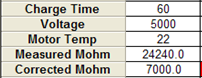
The best meters provide a means of temperature compensation; some even incorporate probes to measure temperature directly. We rely on PdMA equipment in the field, which provides for compensation (see image) as well as useful trending over time. In the shop we use a combination of the Baker AWA and hand held Megger meters depending on the stage of the process. Whatever you choose, pick something user friendly that will encourage accurate readings.
Wrap up
The insulation resistance test is a good, basic test, but it has its limits. The test cannot:
- Determine if a motor is good
- Identify a turn-to-turn fault
- Identify an open phase
- Identify a phase-to-phase fault
IR readings can indicate contamination, deteriorating insulation, and of course a grounded motor. Trending these readings over time will identify changes in insulation and can help plan action before values fall beneath critical limits.
Below are a couple helpful downloads on the insulation resistance test.

View our Motor Repair Best Practices video on Insulation Resistance testing.
Insulation Resistance testing is one of the most basic motor electrical test procedures that can be conducted in the field or in the shop. Yet it’s often overlooked as a source of valuable information, and it’s often misapplied due to some misunderstood fundamentals that must be observed when conducting an IR test.
This is the second in our series of motor repair best practices videos, designed to help you improve motor repair procedures, optimize your investment in motors and ultimately extend the life of this most critical asset. Video highlights the benefits and limitations of Megger testing and discusses more advanced insulation resistance testing performed in a qualified motor repair shop.
