


Surge Testing - Motor Repair Best Practices
Surge testing helps identify a shorted motor conductor turn and as such is a powerful predictor of future motor failure due to turn-to-turn shorting.
Failure of conductor insulation is the culprit here and is one of the first signs that a motor is going to electrically fail. The root cause is often insufficient insulation on the windings, especially at the turns. This can happen during manufacturing, or in the process of re-winding a motor. For motors in service, insulation failure can be due to a variety of factors. Chemical deposits on the windings will break down insulation. Movement of the winding during start-ups can cause excess wear on the insulation. Both of these conditions lead to wearing away of the insulation and inevitably, motor failure.
Because 80% of electrical motor failures start out as turn-to-turn faults, surge testing needs to be part of a comprehensive maintenance program. The surge test is conducted with a Baker Type Testing Machine, following accepted procedures. In brief, that process includes connecting the test machine to the load side of the motor starter. A voltage pulse is placed across a pair of the windings. The test is then repeated for all three pairs of windings to enable a good comparison.
One of the problems we see is a misunderstanding of the proper voltage levels to be used during the test. Many shops incorrectly assume that the voltage applied should be the same as for overvoltage testing. This is incorrect. The old formula of 2e+1000 is wrong. Some manufacturers will even quote the two times voltage plus 1000 formula. Their documentation is not included here out of consideration for the many fine things they do provide.
Understanding the correct testing standard
The standard for surge testing, which is defined by IEEE 522 states in part that "testing is for the dielectric strength of insulation separating the various turns from each other within a form wound coil to determine their acceptability." Test levels described in IEEE 522 "do not evaluate the ability of the turn insulation to withstand abnormal voltage surges, only surges associated with normal operation." Note the phrase "surges associated with normal operation". The problem comes when excessive voltage is applied to the windings.
To calculate the correct level of voltage, you have to define the type or condition of the coils, as shown below.
Once you determine the correct voltage level for the type and condition of the winding, you then consult a chart like the following for the proper voltage to be applied during the surge test. Levels are consistent with IEEE 522.
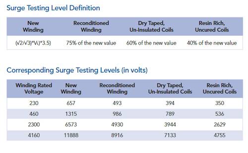
The above chart demonstrates that the old formula (2e+1000), two times the rated voltage plus 1000, will yield too much voltage being applied to the winding during the surge test. This approach is not only potentially injurious to the windings, but can lead to false results. If your shop is not using the recommended standard when performing surge tests, you will want to evaluate the standards they are using. An ideal surge test, when viewed on an oscilloscope will display a uniform looking waveform, indicating that all three sets of windings are acceptable. Review surge testing procedures with your motor shop for longer motor life.