


Motor Repair Best Practices Part 1 – Motor Rotor Balancing
Motor rotor balancing can be a confusing topic leading to sometimes heated conversation, especially in motor shops where cultures have evolved so differently over the years.
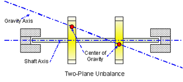
Image Courtesy National Instruments
All rotors must be balanced, whether new from the factory OEM or recently repaired. But the methods of balancing vary, as does the quality of the work. In this post we will examine balancing standards and how you can ensure you get a quality repair.
How motor rotor balancing affects motor life.
Many motor failures are mechanical and associated with the rotor and bearings, so balancing has a direct effect on the life of the motor and productivity. The degree to which a motor is out of balance is referred to as imbalance. Rotor imbalance creates force on the bearing assembly, resulting in vibration and heat. Old style pagers, for example, used small motors that were very imbalanced to create a vibration in your pocket. Like a vibrating pager, extreme imbalances are east to identify. Precision rotor balancing, however, is about very small imbalances. They have an accumulative effect over time, stressing lubrication and bearings.
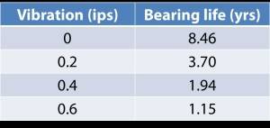
Imbalance can be measured in multiple ways. Vibration (inches per second, ips) is used in the field to assess imbalance as well as other problems. Studies, like this one (figure at right) from CSI show that decreasing vibration from .4 ips to .2 ips will almost double bearing life. Most maintenance teams know how to measure vibration on a running motor, and like us many probably use a CSI to do it. However, correcting rotor imbalance in the shop is a different process than simply checking vibration.
The ISO 1940 Standard for balancing
Balancing machines are designed to precision balance rotating assemblies so there will be minimal vibration when assembled and running at rated speed. The trick is, a rotor is balanced while unassembled and rotating at much slower than rated speed, so the method and technology used is very important. Commercial rotor balancing equipment manufacturers, such as Dyna-Bal, infer NEMA standards. NEMA MG1 section 7, defines limits in displacement, velocity, and acceleration. These are limits of vibration which can easily be measured during a test run of an assembled motor. EASA AR-100 requires the method defined by ISO-1940. This method calculates the force on the bearing, which is a much more accurate method when balancing a slow turning unassembled rotor.
We actually compared both methods in a test. Using the same rotor after balancing to BETTER than NEMA standards, the ISO method decreased average bearing force (between right and left sides) by 49%. Here are a few observations:
- Both methods can describe balance conditions in terms of travel (mils) and each has a means of projecting force on the bearing (oz-inches).
- The ISO method requires rotor weight as an entry point.
- The NEMA limit is simply in mils.
- The ISO limit is in force measured in oz-in. This is a big difference, which is why weight is required.
ISO also provides balancing guidelines in what is referred to as the G scale. A rotor balanced to G2.5 for example will vibrate at 2.5 mm/sec while rotating at rated speed and suspending on a free standing mount. The guideline for motors operating at 1800 RPM and below is G2.5, while 3600 RPM motors are typically balanced to G1.0. The formula is simply expressed as:
[(Balance Grade) x (Weight) / (Rated RPM)] =
Max allowable imbalance per plane in units of force (oz-in).
Quality – motor rotor balancing in the shop
If you ever visit a motor shop, pay close attention to the balancing station. Many of our customers are doing this as part of qualifying their vendors. Why? One possibility is that as techs have retired, shops are turning to the balance machine OEMs for instruction, and they are being referred to the wrong standard. This is why well written procedures and documented training programs are so important. It’s easy to spot an ISO compliant balancing station if you know what to look for.
- ISO requires a regular specific calibration to a defined method, and there will be a calibration certificate typically displayed at the machine. We highly recommend Precision Balancing Company in Indiana.
- ISO requires that the machine itself, as a system, is certified. There should be a certificate for this from an accredited ISO lab.
- You should also see means of easily weighing rotors, and precision scales for measuring corrective weights.
- Note the shaft stops (adjustable piping with ball bearing end) in the photo. This controls movement while not introducing force into the assembly during test.
- Lastly, there should be a written procedure to correctly balance, with conditions, and technicians should be able to accurately describe it.
Check out our Motor Rotor Balancing video for a demonstration of best practices.
